1. Clockwise rotation is standard, viewed from the shaft end.
2. The pump shaft must be installed horizontally. To ensure correct alignment between the pump and motor shafts, the eccentricity between them must be kept within 0.05mm, and the error in the eccentric angle must be kept within 1°. Avoid adding radial and axial loads to the shaft end. In addition, please use sufficiently rigid material as the mounting bracket.
3. Secure the pipeline according to the interface dimensions, especially the inlet pipe; the inlet pipe must be strictly sealed and must not leak.
The system should be equipped with a cooling device (if there is no cooling unit, the oil tank capacity should be increased)
The oil tank should be equipped with a diaphragm to separate bubbles and dirt from the oil;
The oil return nozzle should be below the liquid level, with a minimum depth of 50 mm, to avoid bubble formation even at low levels. Inlet
The pressure should be -0.03 to +0.03MPa; if the pump is installed on the oil tank or above the oil tank cover, the suction port height of the pump should
be less than 500mm.
4. The drainage connection must be directly piped to the oil tank and below the oil level, and the back pressure must not exceed 0.03MPa.
5. P-Q setting value at the time of shipment:
·Flow setting: Maximum flow rate as shown in the catalog.
·Pressure setting: Minimum working pressure range.
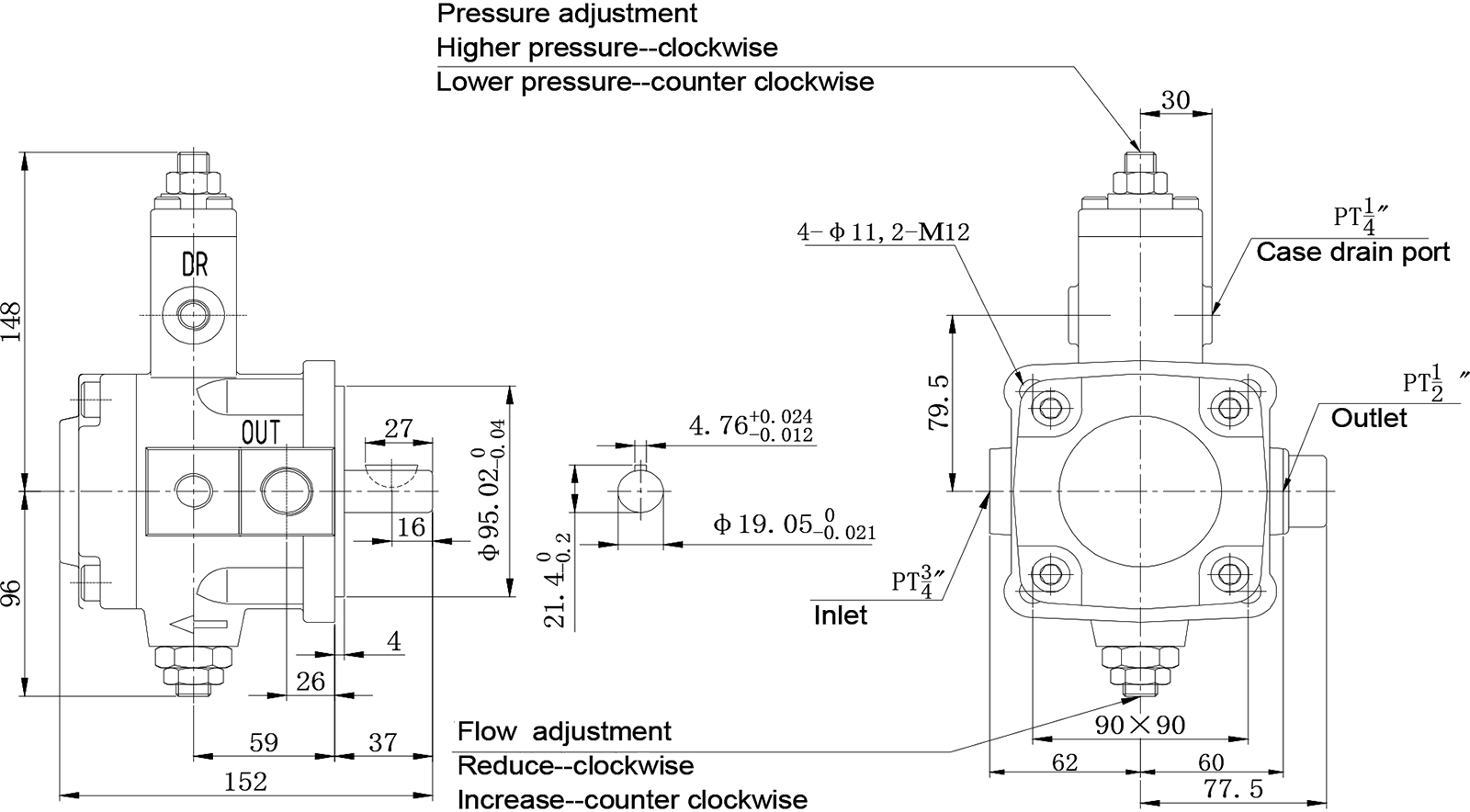
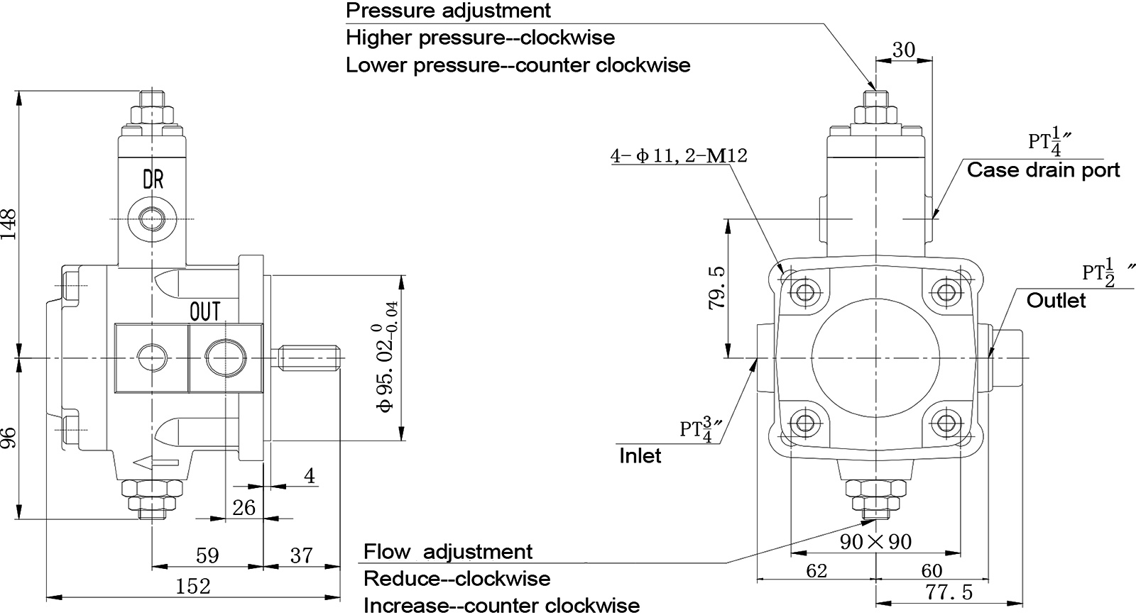
6. Flow and pressure adjustment:
When adjusting, first loosen the locking nut, then rotate the screw, and tighten the locking nut after adjustment.
·When the flow adjusting screw is rotated clockwise, the flow rate will decrease, and when rotated counterclockwise, the flow rate will increase.
·When the pressure adjusting screw is rotated clockwise, the pressure will increase, and when rotated counterclockwise, the pressure will decrease.
7. Thrust Bolt
The thrust bolt is set during pump assembly and should not be adjusted.
8. Hydraulic Oil:
·Use 30 ~ 50cSt (ISO VG32) hydraulic oil at 40 ℃.
·The hydraulic oil temperature range is 15 ~ 60 ℃. If the initial oil temperature is below 15 ℃, please use low-pressure operation to raise the oil temperature to 15 ℃.
9. The oil should be kept clean, and the pipelines and oil tank must be thoroughly cleaned. A precision filter with an accuracy of 25μm should be assembled in the system, and the cleanliness level of the oil should be within NSA10; install a filter with sufficient capacity (the rated flow rate should be more than twice the pump flow rate) above 50mm of the pump inlet, and the recommended accuracy is 100μm (150 mesh).
10. To ensure sufficient lubrication of the pump sliding surface, please fill the pump body before operation.
11. First use: Start the pump under no-load conditions, and repeatedly start and stop the motor several times to exhaust the air inside the pump and pipeline. Then keep running continuously for 10 minutes for better exhaust. For the exhaust pipe, install an exhaust valve.
Installation Connection Dimensions
Single Pump


.png")