

Products
.png")
25V vane pump, lower noise
Key words:Hydraulic tools
Details
Specification
| Subsidiary |
Displacement |
Geometry |
Use anti-wear oil or |
Water-ethylene glycol liquid |
Oil-in-water emulsion |
Min.speed |
Weight |
|||
| Max.pressure |
Max.speed |
Max.pressure |
Max.speed |
Max.pressure |
Max.speed |
|||||
| 25V |
10 |
32.5 |
17.5 |
1800 (1200) |
16 |
1500 |
7 |
1200 |
600 |
25
|
| 12 |
40 |
|||||||||
| 14 |
43 |
|||||||||
| 15 |
45 |
|||||||||
| 17 |
55 |
|||||||||
| 19 |
59 |
|||||||||
| 21 |
67 |
|||||||||
| 25 |
78.6 |
14 |
14 |
|||||||
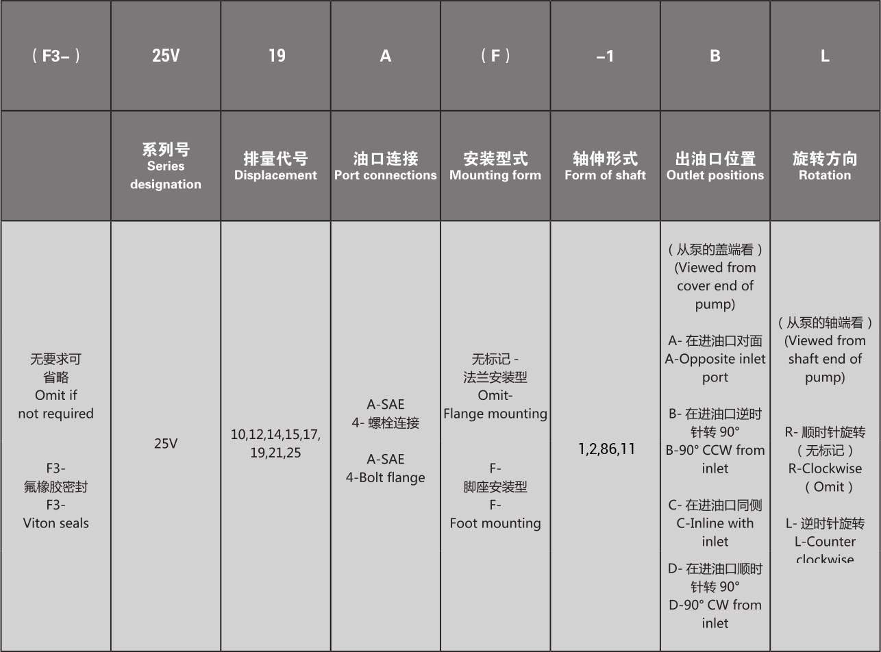
Model Code
Installation and Use
Installation Connection Dimensions


◎ Key Shaft
| Model |
Shaft Cooling |
A |
B |
C |
D |
E |
F Key |
| 25V |
1 |
59 |
9.5 |
11.0 |
22.225/22.20 |
24.5/24.35 |
4.75×32 |
| 2 |
73.2 |
9.5 |
11.0 |
27/26.975 |
30.45/30.32 |
7.94×40 |
|
| 86 |
78 |
9.5 |
11.0 |
25.4/25.37 |
28.3/28.2 |
6.35×50.8 |
◎ Spline Shaft
| Model |
Shaft Cooling |
A |
B |
C |
D |
E |
Spline Data |
||||
| Number of Teeth |
Pitch |
Major Diameter |
Square Root |
Matching |
|||||||
| 25V |
11 |
44.5 |
9.5 |
11.1 |
3.9 |
27.8 |
13 |
22.17/22.15 |
18.63/18.35 |
Major Diameter Fit |
Large diameter fit |
Get Quote
Welcome to leave a message, there may be a discount
Note: Please leave your contact information and our professionals will contact you as soon as possible!


CONTACT US
HOTLINE:
Tel: +86-13968563323 / 13958514945
Add :
No. 118, Luxing Middle Road, Anzhou Street, Xianju County, Zhejiang Province
Email : xjylhmc@163.com / lindawu@chinayongling.com

Official website
SEND A MESSAGE
We will contact you within one working day. Please pay attention to your email.