

.png")
VP22 Variable Displacement Vane Pump
Key words:
Details
Specifications

Model Code

Installation and Use
2.The pump shaft must be horizontally installed. For proper alignment of pump and electric motor shaft,the eccentricity between them must be kept within 0.05mm and the eccentric angle error between them must be kept within 1 ". The shaft ends avoid increasing radial and axial loads. In addition, please use sufficient rigid material as the mounting bracket.
3. Fix pipes, especially inlet pipes, in accordance with the size of port ;
System should be equipped with cooling device (without cooling unit, should increase fuel tank volume);
The fuel tank shall be equipped with a diaphragm to separate the bubbles and dirt from the oil;
The oil return nozzle should be lower the fluid surface, the minimum depth of 50mm, even in a low, too, when the permissible level of to avoid the formation of bubbles;
Inlet port pressure should be -0.03 to +0.03MPa; In case where the pump is installed on the tank or at the position higher than the tank top cover,the height of the suction port of the pump should be less than500mm,
4.Drain connection must be piped directly to tank and below the oil level with a back pressure not exceed 0.03MPa.
5, The setting value of P-Q at the factory:
For adjusting them, first loosen the tightly locked nut, and then spin screws, After adjustment, tighten the lock nut.
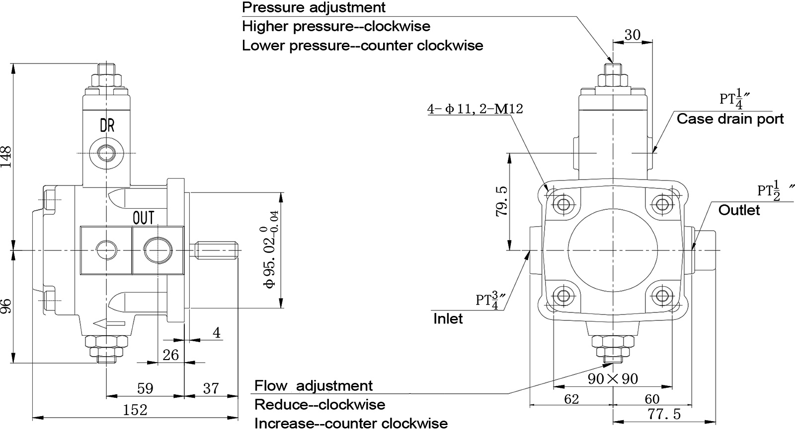
The flow will be reduced when the flow adjusting screw is turned clockwise and increased when anti-clockwise.
The pressure will be increased when the pressure adjusting screw is turned clockwise and reduced when anti-clockwise.
7.Thrust bolt:
The thrust bolts are set when the pump is assembled , Please do not adjust,
8. Hydraulic oil:
Use the hydraulic oil of 30 ~ 50cSt (ISO VG32) at 40℃. The hydraulic oil temperature range of 15 ~60 ℃. Initial oil temperature below 15℃, please use the low voltage operation to oil temperature15C.
9. Oil should be kept clean, pipes and tanks must be thoroughly cleaned.
Precise filters should be assembled with the advised precision of 25μm in the system, the cleanness level of oil should be within NSA10;Fix the sufficient-volume filter (the rated flow rate should be greater than twice the pump flow )at the inlet of the pump 50mm above the bottom of the tank, with the suggested precision of 100pm(150 mesh).
10.To ensure adequate lubrication of the pump sliding surface, please fill the pump body before running.
11. First use :Start up the pump under No-Load condition and repeat to start and stop the motor several times to extract the air from inside of the pump and piping. Then keep a 10 minutes continuous running for a better de-airing. For exhaust pipes, install an exhaust valve.
Installation Connection Dimension

| Module | D.P.16/32 |
| Pressure Angle | 30° |
| Number of Teeth | 9 |
| Pitch Diameter | Φ14.2875 |
| Maximum Diameter |  |
| Minimum Diameter | Φ11.811(MAX) |
Get Quote
Welcome to leave a message, there may be a discount
Note: Please leave your contact information and our professionals will contact you as soon as possible!


CONTACT US
HOTLINE:
Domestic sales:
13968563323/13958514945/13666851636/13968535901/
+86-13968532998/13968565668/13968552819
Foreign sales:+86-576-87759616
Domestic sales:+86-576-87759882
FAX:
+86-576-87827561
Add :NO.118 Luxing Middle Road, Anzhou Street, Xianju, Zhejiang, China
Email : xjylhmc@163.com / lindawu@chinayongling.com
SEND A MESSAGE
We will contact you within one working day. Please pay attention to your email.